Pocket Sized Temperature and Humidity Monitor - Planning
Project Overview⌗
I recently moved into a new place which has historically had issues with mould growth. As part of the preventative measures, I’m planning on building a set of temperature and humidity monitors that I can place around the house and keep track of how at risk rooms are over time. They need to be reasonably small, but can be mains-powered as there will be an outlet in every room I plan to monitor.
In the future, I plan on using the data gathered through these sensors to control individual radiator controls to keep each room at the ideal temperature, for this reason I plan to gather data once every five minutes. It needs to be overall low maintenance so I can set them and forget them.
Initial Plans⌗
The initial plan is to base the project around the ESP8266 which will do the processing and sending of data. This will connect to the IOT wifi network separated from the rest of the house and report to an MQTT server. On the circuit board, there’s going to be:
- A very simple voltage-regulator based power supply which will determine the range of voltages accepted.
- The sensors.
- Two buttons, one to reset and one to place the board into programming mode.
- A barrel jack socket for the power supply.
- A micro-usb socket for programming.
- A power LED.
- LED’s for Tx and Rx.
The Monitors will log to an MQTT server running on a raspberry pi which will also run custom software to archive that data to storage. I haven’t yet decided whether to use grafana to display the data or get homeassistant running and connect that to the MQTT server, though at this point it doesn’t much matter as the only thing that changes is the processing software which will be written towards the end of the project.
As far as the sensors go, I’m planning on using the Adafruit RHT03 As it does both Temperature and Humidity in one package. I’ve also had previous experience with the DHT library which also supports the RHT03.
The requirements for the voltage regulator aren’t too much. The ESP8266 current is likely to use ~100mA so a UA78M33CKCS will do perfectly as it gives 500mA max current. It also accepts anywhere between 5.3v and 25v as input which gives us plenty of flexibility with choosing the power supply.
Instead of having the flashing functionality built in to each chip board (which would add around £5/board), I’m going to create an interface between each of the boards and a dedicated flashing board which will both save me from having to wire up one of the off-the-shelf boards each time and also not have to pay an extra £5/board. I’ll use a second microusb->microusb cable between the two sides, however it won’t be talking USB but will just be used for the wiring and the known connector.
Circuit Designing⌗
I like to start my circuit designing by making sure that I have all of the custom parts downloaded for my editor. I’m using KiCad so need to download the part files for:
- Voltage Regulator (UA78M33CKCS)
- Barrel Jack (RS 122-4879)
- Micro-usb Socket (RS 714-2344)
- Buttons (RS 479-1429)
- ESP8266
- RHT03
All of which are linked to in the above list. With those downloaded, I created the schematic and layed out the circuit board. The Kicad files used to do will be on my github when the boards have been tested (next couple of posts). Screenshots of the final created schematic and board are below.
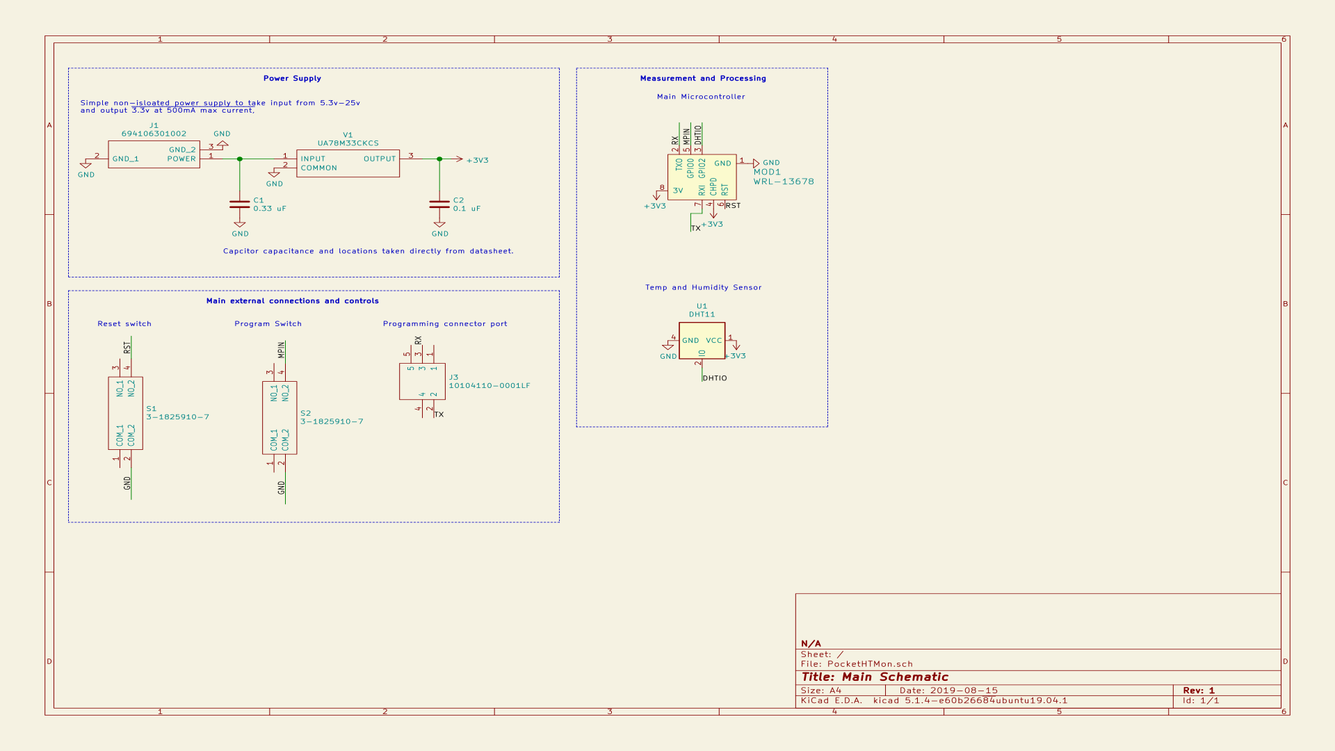
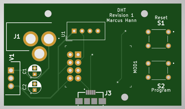
Parts Used (BOM)⌗
| Name | Part Number | Price | Quantity | Total |
|---|---|---|---|---|
| Capacitor (330nF) | RS 707-5650 | 0.034 | 1 | 0.034 |
| Capacitor (100nF) | RS 707-5648 | 0.039 | 1 | 0.039 |
| Tactile Switches | 1825910-7 | 0.079 | 2 | 0.158 |
| Barrel Jack | 694106301002 | 0.744 | 1 | 0.744 |
| Micro USB Connector | 10104110-0001LF | 0.58 | 1 | 0.58 |
| ESP 8266 | WRL-13678 | 5.70 | 1 | 5.70 |
| TH Sensor | SEN-10167 | 8.15 | 1 | 8.15 |
| 8 | 15.405 |